I have been interested in building contraptions and technology almost my entire life. I enjoy and still enjoy putting together Lego sets and coding games. After getting the chance to learn about electronics in my high school, I fell in love with electronics. For a while now, I have been wanting to do a somewhat large project, and I decided to do one for my blog. One of my favorite movie franchises is Star Wars and my favorite droid is BB-8, so I thought that making him would be perfect for a first-time large project.
The Game Plan for Building BB-8
My journey started when I stumbled across a video on YouTube called Build A Life-Size BB8 Droid (Phone Controlled) by TechBuilder. While watching the video, I realized that this project would be easy enough to build at home, so I started making my own design with a couple of changes from the video. The biggest change was using a custom remote for driving instead of using an app. All the other changes were differences in materials and components used.
Materials and Components Used
For the brains of this whole design, I decided to go with the Arduino nano 33 IoT since the board has Wi-Fi, Bluetooth, a gyroscope, and an accelerometer all baked in. Another reason was just because I already had one of them lying around. My design has one Arduino inside of the droid and one for the remote with both connecting to each other through Bluetooth. For the motors, I went with two Pololu micro metal gearmotors, and to control the motors, I decided to use a Dual TB6612FNG Motor Driver board from SparkFun.
The circuit in the droid is powered by 4 AA batteries for the motors, and a 9V battery for the Arduino nano. I used a standard joystick, push buttons, a red LED, a green LED, and 9V battery for the remote. The LEDs are used to indicate the status of whether the boards are connected or not. Instead of making the custom ball like in the video, I decided to use a Styrofoam ball which is slightly smaller, but still works for this project. I also used half of a Styrofoam ball for the head with an ornament cut in half as the eye. I used neodymium magnets to connect the head to body, and cardboard for the base inside the ball. Lastly, I chose to 3D print custom wheels for the motors.
The Process of Building BB-8
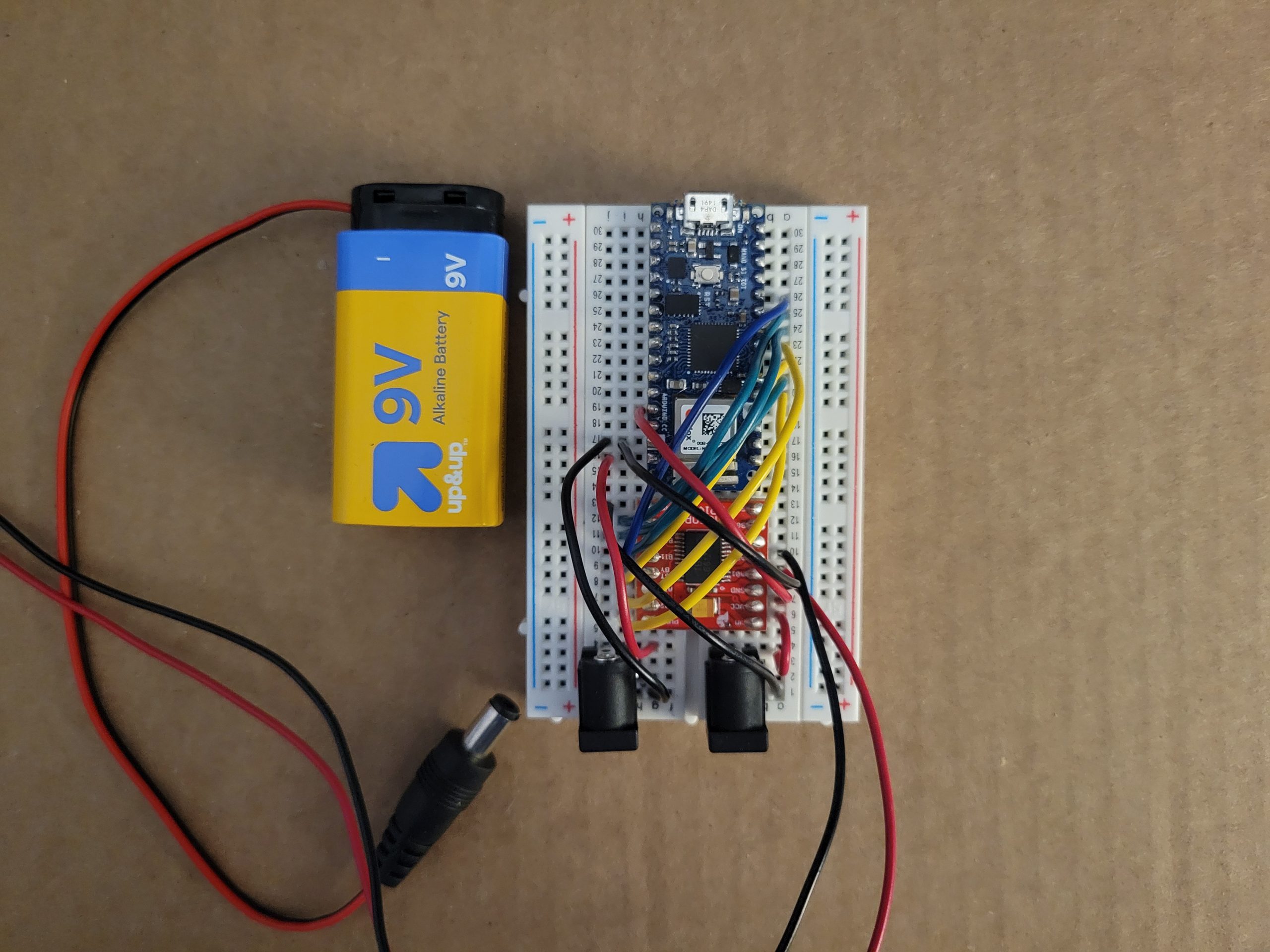
The first step of the process is to put together the circuit for the body. The circuit includes an Arduino nano 33 IoT, the Dual TB6612FNG Motor Driver, the two Pololu gearmotors, a 9V battery, and 4 AA batteries.
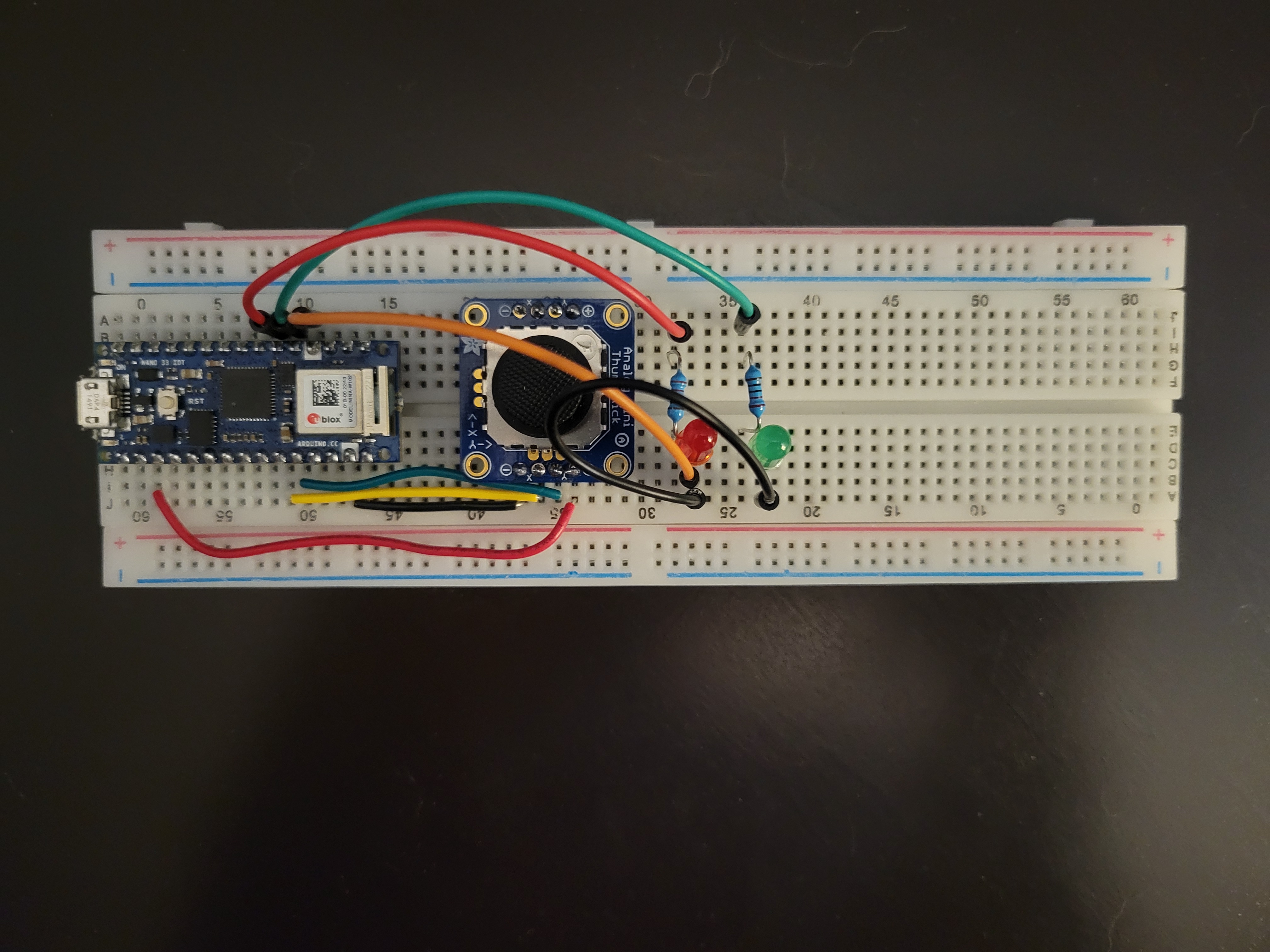
The second step is to build the remote that is used to move the droid. The circuit includes an Arduino nano 33 IoT, a joystick, two push buttons, and a 9V battery.
The third step is to program both Arduino nano boards to have them send data to each other through Bluetooth, so that the remote can move the motors. Below is the code for both boards.
					// BB-8 Controller

#include <ArduinoBLE.h>

const int joyX = A7;
const int joyY = A6;

const int potPin = A5;

const int deadZone = 100;
const int centerValue = 512;

const int directionThreshold = 200;

const int green = 2;
const int red = 3;

void setup() {
  Serial.begin(9600);

  pinMode(green, OUTPUT);
  pinMode(red, OUTPUT);
  digitalWrite(green, LOW);
  digitalWrite(red, LOW);

  BLE.begin();

  Serial.println("Bluetooth® Low Energy Central - LED control");

  BLE.scanForUuid("19b10000-e8f2-537e-4f6c-d104768a1214");
}

void loop() {
  // check if a peripheral has been discovered
  BLEDevice peripheral = BLE.available();

  if (peripheral) {
    Serial.print("Found ");
    Serial.print(peripheral.address());
    Serial.print(" '");
    Serial.print(peripheral.localName());
    Serial.print("' ");
    Serial.print(peripheral.advertisedServiceUuid());
    Serial.println();

    if (peripheral.localName() != "LED") {
      return;
    }


    BLE.stopScan();

    controlLed(peripheral);

    BLE.scanForUuid("19b10000-e8f2-537e-4f6c-d104768a1214");
  }
}

void controlLed(BLEDevice peripheral) {
  Serial.println("Connecting ...");

  if (peripheral.connect()) {
    Serial.println("Connected");
    digitalWrite(red, LOW);
    digitalWrite(green, HIGH);
  } else {
    Serial.println("Failed to connect!");
    digitalWrite(green, LOW);
    digitalWrite(red, HIGH);
    return;
  }
  Serial.println("Discovering attributes ...");
  if (peripheral.discoverAttributes()) {
    Serial.println("Attributes discovered");
  } else {
    Serial.println("Attribute discovery failed!");
    peripheral.disconnect();
    return;
  }

  BLECharacteristic ledCharacteristic = peripheral.characteristic("19b10001-e8f2-537e-4f6c-d104768a1214");

  if (!ledCharacteristic) {
    Serial.println("Peripheral does not have LED characteristic!");
    peripheral.disconnect();
    return;
  } else if (!ledCharacteristic.canWrite()) {
    Serial.println("Peripheral does not have a writable LED characteristic!");
    peripheral.disconnect();
    return;
  }

  while (peripheral.connected()) {
    int xValue = analogRead(joyX);
    int yValue = analogRead(joyY);
    int potVal = analogRead(potPin);

    Serial.print("X: ");
    Serial.print(xValue);
    Serial.print(" Y: ");
    Serial.println(yValue);

    if (xValue < centerValue - directionThreshold) {
      // Joystick pushed left
      ledCharacteristic.writeValue((byte)0x01);
    } else if (xValue > centerValue + directionThreshold) {
      // Joystick pushed right
      ledCharacteristic.writeValue((byte)0x02);
    } else if (yValue < centerValue - directionThreshold) {
      // Joystick pushed up
      ledCharacteristic.writeValue((byte)0x03);
    } else if (yValue > centerValue + directionThreshold) {
      // Joystick pushed down
      ledCharacteristic.writeValue((byte)0x04);
    }
    else {
      ledCharacteristic.writeValue((byte)0x00);
    }
  }

  Serial.println("Peripheral disconnected");
  digitalWrite(green, LOW);
  digitalWrite(red, LOW);
}
					// BB-8 Motor Driver

#include <ArduinoBLE.h>

BLEService ledService("19B10000-E8F2-537E-4F6C-D104768A1214");

BLEByteCharacteristic switchCharacteristic("19B10001-E8F2-537E-4F6C-D104768A1214", BLERead | BLEWrite);

const int PWMA = 2;
const int PWMB = 3;
const int AIN1 = 4;
const int AIN2 = 5;
const int BIN1 = 6;
const int BIN2 = 7;
const int STBY = 8;

void setup() {
  Serial.begin(9600);

  pinMode(PWMA, OUTPUT);
  pinMode(PWMB, OUTPUT);
  pinMode(AIN1, OUTPUT);
  pinMode(AIN2, OUTPUT);
  pinMode(BIN1, OUTPUT);
  pinMode(BIN2, OUTPUT);
  pinMode(STBY, OUTPUT);

  if (!BLE.begin()) {
    Serial.println("starting Bluetooth® Low Energy module failed!");

    while (1);
  }

  BLE.setLocalName("LED");
  BLE.setAdvertisedService(ledService);

  ledService.addCharacteristic(switchCharacteristic);

  BLE.addService(ledService);

  switchCharacteristic.writeValue(0);

  BLE.advertise();

  Serial.println("BLE LED Peripheral");
}

void loop() {
  BLEDevice central = BLE.central();

  if (central) {
    Serial.print("Connected to central: ");
    Serial.println(central.address());

    while (central.connected()) {
      if (switchCharacteristic.written()) {
        if (switchCharacteristic.value() == (byte)0x00) {
          digitalWrite(STBY, HIGH);
          analogWrite(PWMA, 0);
          analogWrite(PWMB, 0);
          digitalWrite(AIN1, LOW);
          digitalWrite(AIN2, LOW);
          digitalWrite(BIN1, LOW);
          digitalWrite(BIN2, LOW);
        }
        if (switchCharacteristic.value() == (byte)0x01) {
          digitalWrite(STBY, HIGH);
          analogWrite(PWMA, 255);
          analogWrite(PWMB, 255);
          digitalWrite(AIN2, LOW);
          digitalWrite(BIN1, LOW);
          digitalWrite(AIN1, HIGH);
          digitalWrite(BIN2, HIGH);
        }
        if (switchCharacteristic.value() == (byte)0x02) {
          digitalWrite(STBY, HIGH);
          analogWrite(PWMA, 255);
          analogWrite(PWMB, 255);
          digitalWrite(AIN1, LOW);
          digitalWrite(BIN2, LOW);
          digitalWrite(AIN2, HIGH);
          digitalWrite(BIN1, HIGH);
        }
        if (switchCharacteristic.value() == (byte)0x03) {
          digitalWrite(STBY, HIGH);
          analogWrite(PWMA, 255);
          analogWrite(PWMB, 255);
          digitalWrite(AIN2, LOW);
          digitalWrite(BIN2, LOW);
          digitalWrite(AIN1, HIGH);
          digitalWrite(BIN1, HIGH);
        }
        if (switchCharacteristic.value() == (byte)0x04) {
          digitalWrite(STBY, HIGH);
          analogWrite(PWMA, 255);
          analogWrite(PWMB, 255);
          digitalWrite(AIN1, LOW);
          digitalWrite(BIN1, LOW);
          digitalWrite(AIN2, HIGH);
          digitalWrite(BIN2, HIGH);
        }
      }
    }

    Serial.print(F("Disconnected from central: "));
    Serial.println(central.address());
  }
}
The fourth step is to test everything to make sure everything was coded and wired correctly.
The fifth step is to put all the components onto a cardboard base that will then be put inside the Styrofoam ball. The wheels are put on the motors, and everything is secured to the base. This is the step I am currently working on.
The sixth step is to put a cardboard tube on top of the base and then put a magnet on top of the tube. The magnet should be almost touching the inside of the ball.
The seventh step is to make the head by gluing on the ornament and painting on the design. I decided to make the head early, so here is a picture of it below.
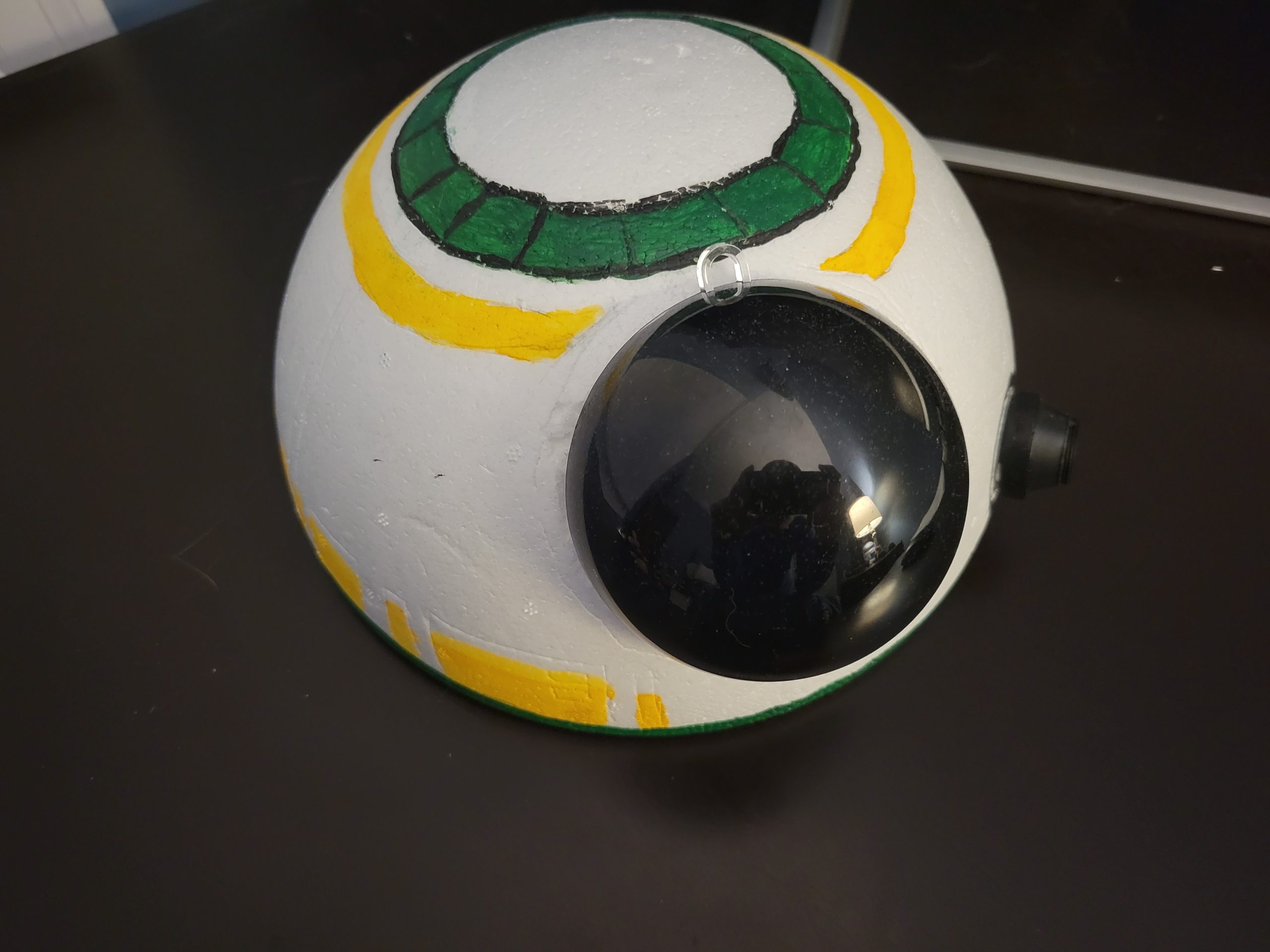
The eighth and final step is to attach a magnet to the bottom of the head and then connect the two magnets together through the Styrofoam.
Struggles and Troubleshooting
The problem I ran into was with making the body. I know that I just said a Styrofoam ball for that body, but the was not what I wanted to do when I started this project. I initially tried to make the same custom ball that was in the video, but canvas material for the middle layer of the body was not cooperating with me and was not sticking well. After trying for a couple days, I eventually just decided to go with the Styrofoam ball.
Another problem that I had was getting the wheels. I asked a friend if he would be able to model and print the wheels for this project, and he said yes. He was able to model the wheels easily, but the problems started coming up when printing. First, the printer refused to connect to the computer. Second, when the printer was fixed, the first iteration of the wheels did not fit onto the motor. Third, after fixing the model and the wheels started printing, the printer jammed.
Final Product
I am still currently working on it, but here are some of the things I would want to improve or change if I decided to do version 2. One thing I would want to improve would be putting all the electronic components onto a printed circuit board (PCB) for both inside the droid and for the remote control. Another thing I would want to improve would be having stronger connection between the body and the head whether it is having stronger magnets or a thinner material for the ball.
One thing I would want to add would be an mp3 player with a speaker to play different sound effects. Another thing I would want to add would be LEDs for the eye and other parts of the head. Lastly, I would want use only one power source on the inside of the droid.
Conclusion
My passion for technology and electronics, combined with my love for Star Wars, led me to create BB-8 as my first large project. This project allowed me to combine my skills in building, coding, and electronics. By creating a blog based on this project, I want to inspire others to pursue their own creative projects and explore different technology.